 Packet Power Team
1 min read
Split-Core CTs and Why Size Matters
Current transducers (CTs) are a critical component of power monitoring. They come in a variety of formats, sizes, current ratings and accuracy...

HEAR FROM OUR CUSTOMERS
Check out these real world examples of how Packet Power transformed our customers’ operations.

STAY UP-TO-DATE WITH OUR BLOG
Keep up with the latest innovations and trends in energy and environmental monitoring.

LOOKING FOR HELP?
Our technical support team is happy to assist.

Current Transducers are a key component of every power monitoring system. If you have ever wondered why they are used or how they work, here's a quick review of alternating current transducer basics.
Current transducers are used to measure current on circuits. They operate by magnetically inducing current from the conductor they are placed on into a proportional electric current that flows through the CTs back to the power meter. They make it possible for power meters to accurately measure Current (Amps) on electrical circuits. If you want to monitor power, you need to use CTs.
Guide to Data Center Monitoring

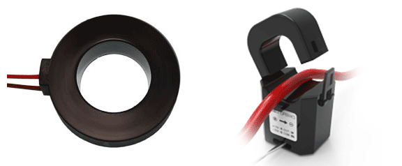
Split-core CTs have a "split" in the core that allows the CTs to open and be placed around the conductor without having to disconnect the conductor or disrupt the wiring. Split core CTs may be more expensive, but their convenience generally outweighs their cost when dealing with retrofit installations.

Solid core CT Split core CT
Most CTs are labeled according to their nominal current rating. It's important to use a CT rated as close to the actual current as possible to attain the CT’s accuracy at the lowest possible load.
Selecting the optimal current rating for a CT should be based on expected minimum, average, and maximum loads. Consider a case where the circuit has a 100 amp breaker. If a 70A nominal rated CT, accuracy Class 1.0, is used (with an 84A maximum capacity), the CT will be accurate down to a 3.5A load versus a 100A nominal rated CT that will be accurate down to a 5A load. This may be desired only if the circuit is lightly loaded. Any time the circuit experiences a current of 84A or more, it will not be measured accurately with a 70A CT, and the CT may be damaged.
CTs are available in a variety of accuracy classes ranging from 0.1% to 5% error. Typical CTs have an accuracy of 1% (referred to as Class 1.0), which is also recognized by Utility providers. Accuracy will be expressed over a specific load range. In the case of a 1% rated CT, accuracy is expressed over a measurement range of 5 to 120% of the CT's nominal current rating. So a class 1.0 CT with a nominal rating of 100 amps will provide 1% accuracy from 5 to 120 amps of current.
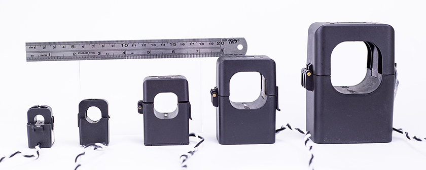
Pay attention to the inside diameter of the CT. This describes the size of the opening inside the CT. If you try to use a CT with too small of an inside diameter, it won't fit around the conductor. If it’s too large, it won’t be as accurate. Also take into account any physical space constraints or parallel conductors. In certain environments or larger conductor sizes, Rogowski coils make for a nice alternative where traditional CTs may not be suitable.
CTs will natively have a current output such as 1A or 5A representing the output value at the nominal rating of the CT. Shunted CTs use an internal resistor (shunt) to create a voltage output such as 0.33V versus a current output. Current output CTs can produce exceptionally high and dangerous voltages when the leads are disconnected and the CT is installed on a live conductor. So shunted CTs offer a safety advantage and are preferred on higher power circuits.
One of the most common mistakes in CT installation is misorientation. CTs need to be oriented with a specific side facing towards the power source and away from the load. CTs will generally have placement indicators to help orient correctly on the conductor(s). A misoriented CT will result in negative power readings affecting phase angles and power factor. Another best practice is to label your CT leads to eliminate any confusion around where each one will land and avoid the possibility of a dead short circuit.
Packet Power provides a large variety of AC CTs designed to meet your specific requirements. Our power monitoring systems are pre-configured to work with the selected CTs. Our CT leads and flexible CT wire harnesses are built to your specifications and use polarized quick connectors to avoid cumbersome control wiring work in the field.
Packet Power also offers a number of DC CTs for use with our DC power monitors.

1 min read
Current transducers (CTs) are a critical component of power monitoring. They come in a variety of formats, sizes, current ratings and accuracy...

1 min read
You don't know the future cost of energy (otherwise you'd probably be cornering the energy futures markets right now). But it's a safe bet energy...

1 min read
You've decided to monitor energy use in your facility. The good news is that you've got a number of options to do this. The not-so-good news is that...